
🔵 WHY ARE THE MIRRORS OF JAMES WEBB SPACE TELESCOPE (JWST) GOLDEN❓
▶️ Gold is a good infrared reflector, and JWST is designed to observe infrared light for observing the oldest galaxies in the universe. Hence, a 100 micrometre thin layer of Gold is applied to mirrors.
━━━━━━━━━━━━
☢ @Physics ⚡| @Education 📖
▶️ Gold is a good infrared reflector, and JWST is designed to observe infrared light for observing the oldest galaxies in the universe. Hence, a 100 micrometre thin layer of Gold is applied to mirrors.
━━━━━━━━━━━━
☢ @Physics ⚡| @Education 📖

🔥29👍22❤14🎉5
The field-effect transistor (FET) is a type of transistor that uses an electric field to control the flow of current in a semiconductor. FETs (JFETs or MOSFETs) are devices with three terminals: source, gate, and drain. FETs control the flow of current by the application of a voltage to the gate, which in turn alters the conductivity between the drain and source. FETs are also known as unipolar transistors since they involve single-carrier-type operation. That is, FETs use either electrons (n-channel) or holes (p-channel) as charge carriers in their operation, but not both. Many different types of field effect transistors exist. Field effect transistors generally display very high input impedance at low frequencies. The most widely used field-effect transistor is the MOSFET (metal-oxide-semiconductor field-effect transistor).
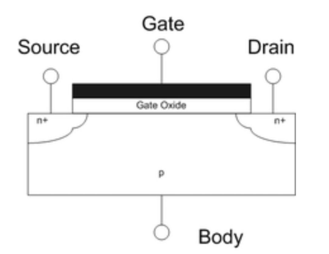
The image down below shows the cross-sectional view of a field-effect transistor, showing source, gate and drain terminals.
━━━━━━━━━━━━
☢ @Physics ⚡| @Education 📖
The image down below shows the cross-sectional view of a field-effect transistor, showing source, gate and drain terminals.
━━━━━━━━━━━━
☢ @Physics ⚡| @Education 📖
👍23❤11🔥7🤩3😱2🎉2
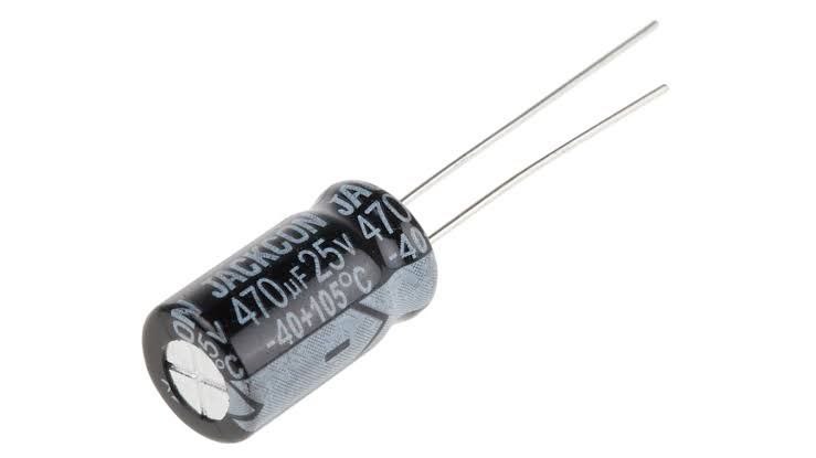
A capacitor is a device that stores electrical energy in an electric field by virtue of accumulating electric charges on two close surfaces insulated from each other. It is a passive electronic component with two terminals.
The effect of a capacitor is known as capacitance. While some capacitance exists between any two electrical conductors in proximity in a circuit, a capacitor is a component designed to add capacitance to a circuit. The capacitor was originally known as a condenser, a term still encountered in a few compound names, such as the condenser microphone.
The physical form and construction of practical capacitors vary widely and many types of capacitors are in common use. Most capacitors contain at least two electrical conductors often in the form of metallic plates or surfaces separated by a dielectric medium. A conductor may be a foil, thin film, sintered bead of metal, or an electrolyte. The nonconducting dielectric acts to increase the capacitor's charge capacity. Materials commonly used as dielectrics include glass, ceramic, plastic film, paper, mica, air, and oxide layers. Capacitors are widely used as parts of electrical circuits in many common electrical devices. Unlike a resistor, an ideal capacitor does not dissipate energy, although real-life capacitors do dissipate a small amount (see Non-ideal behavior). When an electric potential difference (a voltage) is applied across the terminals of a capacitor, for example when a capacitor is connected across a battery, an electric field develops across the dielectric, causing a net positive charge to collect on one plate and net negative charge to collect on the other plate. No current actually flows through the dielectric. However, there is a flow of charge through the source circuit. If the condition is maintained sufficiently long, the current through the source circuit ceases. If a time-varying voltage is applied across the leads of the capacitor, the source experiences an ongoing current due to the charging and discharging cycles of the capacitor.
━━━━━━━━━━━━
☢ @Physics ⚡| @Education 📖
The effect of a capacitor is known as capacitance. While some capacitance exists between any two electrical conductors in proximity in a circuit, a capacitor is a component designed to add capacitance to a circuit. The capacitor was originally known as a condenser, a term still encountered in a few compound names, such as the condenser microphone.
The physical form and construction of practical capacitors vary widely and many types of capacitors are in common use. Most capacitors contain at least two electrical conductors often in the form of metallic plates or surfaces separated by a dielectric medium. A conductor may be a foil, thin film, sintered bead of metal, or an electrolyte. The nonconducting dielectric acts to increase the capacitor's charge capacity. Materials commonly used as dielectrics include glass, ceramic, plastic film, paper, mica, air, and oxide layers. Capacitors are widely used as parts of electrical circuits in many common electrical devices. Unlike a resistor, an ideal capacitor does not dissipate energy, although real-life capacitors do dissipate a small amount (see Non-ideal behavior). When an electric potential difference (a voltage) is applied across the terminals of a capacitor, for example when a capacitor is connected across a battery, an electric field develops across the dielectric, causing a net positive charge to collect on one plate and net negative charge to collect on the other plate. No current actually flows through the dielectric. However, there is a flow of charge through the source circuit. If the condition is maintained sufficiently long, the current through the source circuit ceases. If a time-varying voltage is applied across the leads of the capacitor, the source experiences an ongoing current due to the charging and discharging cycles of the capacitor.
━━━━━━━━━━━━
☢ @Physics ⚡| @Education 📖
👍33🔥16❤8😱2🎉1
A resistor is a passive two-terminal electrical component that implements electrical resistance as a circuit element. In electronic circuits, resistors are used to reduce current flow, adjust signal levels, to divide voltages, bias active elements, and terminate transmission lines, among other uses. High-power resistors that can dissipate many watts of electrical power as heat may be used as part of motor controls, in power distribution systems, or as test loads for generators. Fixed resistors have resistances that only change slightly with temperature, time or operating voltage. Variable resistors can be used to adjust circuit elements (such as a volume control or a lamp dimmer), or as sensing devices for heat, light, humidity, force, or chemical activity.
━━━━━━━━━━━━
☢ @Physics ⚡| @Education 📖
━━━━━━━━━━━━
☢ @Physics ⚡| @Education 📖

🔥16❤12👍12😱6
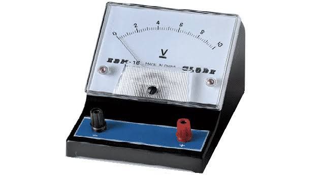
A voltmeter is an instrument used for measuring electric potential difference between two points in an electric circuit. It is connected in parallel. It usually has a high resistance so that it takes negligible current from the circuit.
Analog voltmeters move a pointer across a scale in proportion to the voltage measured and can be built from a galvanometer and series resistor. Meters using amplifiers can measure tiny voltages of microvolts or less. Digital voltmeters give a numerical display of voltage by use of an analog-to-digital converter.
Voltmeters are made in a wide range of styles, some separately powered (e.g. by battery), and others powered by the measured voltage source itself. Instruments permanently mounted in a panel are used to monitor generators or other fixed apparatus. Portable instruments, usually equipped to also measure current and resistance in the form of a multimeter, are standard test instruments used in electrical and electronics work. Any measurement that can be converted to a voltage can be displayed on a meter that is suitably calibrated; for example, pressure, temperature, flow or level in a chemical process plant.
━━━━━━━━━━━━
☢ @Physics ⚡| @Education 📖
Analog voltmeters move a pointer across a scale in proportion to the voltage measured and can be built from a galvanometer and series resistor. Meters using amplifiers can measure tiny voltages of microvolts or less. Digital voltmeters give a numerical display of voltage by use of an analog-to-digital converter.
Voltmeters are made in a wide range of styles, some separately powered (e.g. by battery), and others powered by the measured voltage source itself. Instruments permanently mounted in a panel are used to monitor generators or other fixed apparatus. Portable instruments, usually equipped to also measure current and resistance in the form of a multimeter, are standard test instruments used in electrical and electronics work. Any measurement that can be converted to a voltage can be displayed on a meter that is suitably calibrated; for example, pressure, temperature, flow or level in a chemical process plant.
━━━━━━━━━━━━
☢ @Physics ⚡| @Education 📖
👍25❤12🔥9
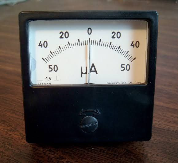
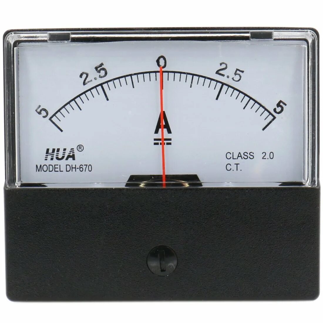
An ammeter (abbreviation of Ampere meter) is an instrument used to measure the current in a circuit. Electric currents are measured in amperes (A), hence the name. For direct measurement, the ammeter is connected in series with the circuit in which the current is to be measured. An ammeter usually has low resistance so that it does not cause a significant voltage drop in the circuit being measured.
Instruments used to measure smaller currents, in the milliampere or microampere range, are designated as milliammeters or microammeters. Early ammeters were laboratory instruments that relied on the Earth's magnetic field for operation. By the late 19th century, improved instruments were designed which could be mounted in any position and allowed accurate measurements in electric power systems. It is generally represented by the letter 'A' in a circuit.
━━━━━━━━━━━━
☢ @Physics ⚡| @Education 📖
Instruments used to measure smaller currents, in the milliampere or microampere range, are designated as milliammeters or microammeters. Early ammeters were laboratory instruments that relied on the Earth's magnetic field for operation. By the late 19th century, improved instruments were designed which could be mounted in any position and allowed accurate measurements in electric power systems. It is generally represented by the letter 'A' in a circuit.
━━━━━━━━━━━━
☢ @Physics ⚡| @Education 📖
👍28🔥8❤6😁2🎉1🤩1
A picoammeter, or pico ammeter, measures very low electric current, usually from the picoampere range at the lower end to the milliampere range at the upper end.
Picoammeters are used where the current being measured is below the limits of sensitivity of other devices, such as multimeters.
Most picoammeters use a "virtual short" technique and have several different measurement ranges that must be switched between to cover multiple decades of measurement. Other modern picoammeters use log compression and a "current sink" method that eliminates range switching and associated voltage spikes. Special design and usage considerations must be observed in order to reduce leakage current which may swamp measurements such as special insulators and driven shields. Triaxial cable is often used for probe connections.
━━━━━━━━━━━━
☢ @Physics ⚡| @Education 📖
Picoammeters are used where the current being measured is below the limits of sensitivity of other devices, such as multimeters.
Most picoammeters use a "virtual short" technique and have several different measurement ranges that must be switched between to cover multiple decades of measurement. Other modern picoammeters use log compression and a "current sink" method that eliminates range switching and associated voltage spikes. Special design and usage considerations must be observed in order to reduce leakage current which may swamp measurements such as special insulators and driven shields. Triaxial cable is often used for probe connections.
━━━━━━━━━━━━
☢ @Physics ⚡| @Education 📖
🔥16❤11👍10
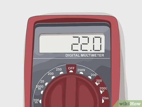
An ohmmeter is an electrical instrument that measures electrical resistance (the opposition offered by a circuit or component to the flow of electric current). Multimeters also function as ohmmeters when in resistance-measuring mode. An ohmmeter applies current to the circuit or component whose resistance is to be measured. It then measures the resulting voltage and calculates the resistance using Ohm’s law (V = IR).
An ohmmeter should not be connected to a circuit or component that is carrying a current or is connected to a power source. Power should be disconnected before connecting the ohmmeter. Ohmmeters can be either connected in series or parallel based on requirements (whether resistance being measured is part of circuit or is a shunt resistance).
Micro-ohmmeters (microhmmeter or micro ohmmeter) make measurements of low resistance. Megohmmeters (also a trademarked device Megger) measure large values of resistance. The unit of measurement for resistance is the ohm (Ω).
━━━━━━━━━━━━
☢ @Physics ⚡| @Education 📖
An ohmmeter should not be connected to a circuit or component that is carrying a current or is connected to a power source. Power should be disconnected before connecting the ohmmeter. Ohmmeters can be either connected in series or parallel based on requirements (whether resistance being measured is part of circuit or is a shunt resistance).
Micro-ohmmeters (microhmmeter or micro ohmmeter) make measurements of low resistance. Megohmmeters (also a trademarked device Megger) measure large values of resistance. The unit of measurement for resistance is the ohm (Ω).
━━━━━━━━━━━━
☢ @Physics ⚡| @Education 📖
👍36❤14🔥10
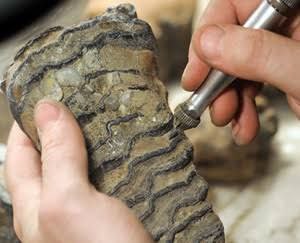
Radiometric dating, radioactive dating or radioisotope dating is a technique which is used to date materials such as rocks or carbon, in which trace radioactive impurities were selectively incorporated when they were formed. The method compares the abundance of a naturally occurring radioactive isotope within the material to the abundance of its decay products, which form at a known constant rate of decay. The use of radiometric dating was first published in 1907 by Bertram Boltwood and is now the principal source of information about the absolute age of rocks and other geological features, including the age of fossilized life forms or the age of the Earth itself, and can also be used to date a wide range of natural and man-made materials.
Together with stratigraphic principles, radiometric dating methods are used in geochronology to establish the geologic time scale. Among the best-known techniques are radiocarbon dating, potassium–argon dating and uranium–lead dating. By allowing the establishment of geological timescales, it provides a significant source of information about the ages of fossils and the deduced rates of evolutionary change. Radiometric dating is also used to date archaeological materials, including ancient artifacts.
Different methods of radiometric dating vary in the timescale over which they are accurate and the materials to which they can be applied.
━━━━━━━━━━━━
☢ @Physics ⚡| @Education 📖
Together with stratigraphic principles, radiometric dating methods are used in geochronology to establish the geologic time scale. Among the best-known techniques are radiocarbon dating, potassium–argon dating and uranium–lead dating. By allowing the establishment of geological timescales, it provides a significant source of information about the ages of fossils and the deduced rates of evolutionary change. Radiometric dating is also used to date archaeological materials, including ancient artifacts.
Different methods of radiometric dating vary in the timescale over which they are accurate and the materials to which they can be applied.
━━━━━━━━━━━━
☢ @Physics ⚡| @Education 📖
👍27🔥9❤8😁1
The temperature and dampness of clouds changes constantly, which affects the shape of each snowflake. Even though snowflakes can change shape so quickly, the hexagonal symmetry is maintained.
━━━━━━━━━━━━
☢ @Physics ⚡| @Education 📖
━━━━━━━━━━━━
☢ @Physics ⚡| @Education 📖

🔥22👍15❤10🎉3